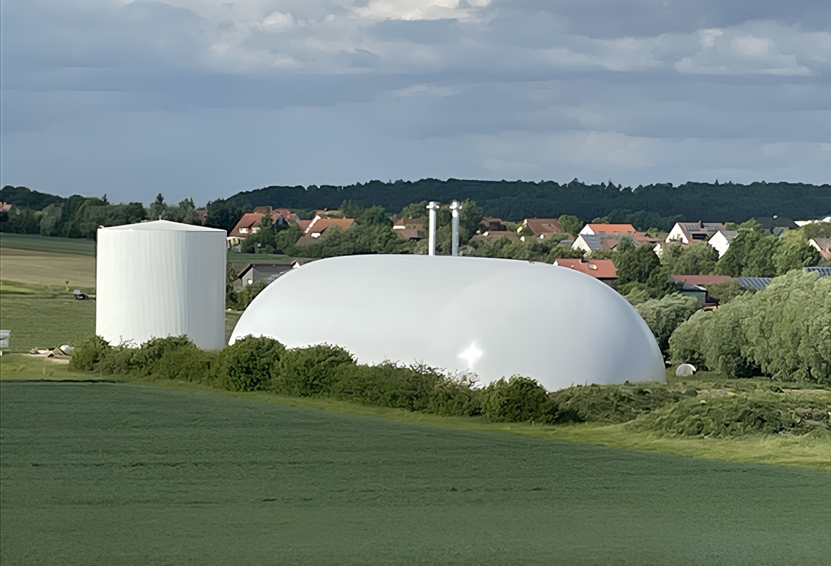
Large-volume double-membrane gas holders — 13,000–100,000 m³
139.300–858.600 €
The double membrane gasholder on a separate concrete foundation buffers differences between biogas production and consumption. It supplies CHP or gas treatment equipment according to the operating schedule. Nominal capacities: 13,000–100,000 m³.
Storage volume and gas throughput are selected separately: more storage extends buffering, not gas production. Blowers, connections and protection are sized for the gas flows and pressure limits.
Geometry and large storage volumes
The elongated dome consists of two quarter-sphere ends and a central half-cylinder. The base cross-section is 30 m wide and 15 m high: H = D/2, where D is the cross-sectional width. To increase storage capacity, the end sections and cross-section are retained while the central section is extended. This increases membrane and floor areas, the length of straight anchoring sections and the required installation footprint.
The 19 nominal sizes cover 13,000–100,000 m³. Usable inventory depends on membrane position; capacity and dimensions are agreed per configuration.
How the double membrane system works
The flexible inner gas storage membrane contains the biogas above a gas-tight membrane floor. It rises as gas enters and descends as gas is withdrawn. The outer weather protection membrane retains its shape through supporting air pressure in the space between the membranes.
A support air blower system supplies this space, while the exhaust air assembly regulates air discharge. The outer dome keeps its shape as stored volume changes. The air system is sized for gas withdrawal and operating pressure.
Membranes, floor and fastening
The outer membrane is made of PVC-coated polyester fabric with UV protection. The black, biogas-resistant inner membrane is made of low-density polyethylene (PE-LD). Material specification, membrane strength and colour are selected for the project and site conditions.
A gas-tight PE-LD floor membrane and protective fleece separate the gas enclosure from its base. The membranes are secured around the separate foundation with bolted double flat profiles made of stainless steel. The package includes the associated fastening and sealing materials. When the gas holder is lengthened, materials for the straight anchoring sections increase in proportion to their length; the end sections remain unchanged.
An external belt system provides additional stabilization under wind loading. An elastic PVC element at the top helps accommodate tension peaks. Wind and snow loads, foundation requirements and anchoring are checked for the site. Permitted operating temperatures are determined by the specifications of the selected membranes.
Filling level measurement and pressure protection
A filling level indicator with a 4–20 mA signal allows the storage level to be integrated into the plant control system. The measurement method and membrane stabilisation arrangement are selected for the installation. Stabilisation reduces uneven membrane movement and improves the reliability of level measurement.
Pressure protection is selected according to gas production, withdrawal and permitted pressure. The base operating pressure is +2 to +3 mbar, with a lower limit of −1 mbar. The 2026 price list allows one mechanical pressure relief valve per started 13,000 m³. Final quantities and settings are checked against gas flow rates and the required overpressure and vacuum protection.
Equipment package and project selection
The complete materials and equipment package comprises the outer and gas membranes, sealed floor, protective fleece, anchoring, belt system, ATEX blowers with air ducts and discharge assemblies, gas connections, membrane suction protection, filling level measurement, calming system, pressure-protection assemblies and service openings. As required throughput increases, more units of the same equipment are used, without increasing the power of each unit. Quantities are recorded in the specification.
Selection requires the storage volume, site dimensions, gas production and withdrawal rates, operating pressure, electrical supply and local climatic loads. Prices are stated in euros excluding VAT. Gas holder materials and equipment are included; the concrete foundation, installation, packaging and delivery are excluded. Specifications, scope and prices are listed separately below.
Specifications
Scope of supply
Project-specific configuration
| Specifications | |
|---|---|
| Application | Biogas storage |
| Construction | Freestanding double-membrane enclosure |
| Shape | Central half-cylinder and two quarter-sphere ends |
| Nominal range | 19 sizes from 13,000 to 100,000 m³; usable capacity specified per project |
| Width and height | Base cross-section: 30 m wide and 15 m high; configuration subject to project design |
| Volume adjustment | Central-section length changes with the selected cross-section retained |
| Installation base | Concrete foundation; foundation excluded from supply |
| Gas and bottom membranes | Biogas-resistant PE-LD |
| Outer membrane | PVC-coated polyester fabric, UV-protected, finished on both sides |
| Outer membrane grade | 6000N — material designation in the large gas holder specification |
| Protective ground layer | Protective fleece |
| Anchoring | Double stainless-steel clamping profiles |
| Enclosure stabilization | Support air and external belt system |
| Blowers | ATEX-rated; quantity, capacity and electrical supply specified per project |
| Level measurement | 4–20 mA output |
| Pressure measurement | Connection flange; measuring equipment specified per project |
| Overpressure protection | Mechanical dry-type relief valves; size and quantity specified per project |
| Dimensions, pressure and gas flow rates | As agreed for the selected configuration |
| Outer membrane colour | By agreement |
| Operating pressure, mbar | Base +2 to +3; lower limit −1; final values specified per project |
| Temperature, snow and wind loads | According to membrane specifications and site-specific design |
Membrane material properties
Datasheet values for the documented 0.8 mm PE-LD membrane and 4000/4000 N/5 cm PVC-coated fabric. The large gas holder specifies a 6000N outer membrane; its properties are defined by the datasheet of the selected material.
PE-LD gas membrane, 0.8 mm
- Material: Low-density polyethylene, PE-LD
- Thickness: 0.8 mm
- Mass per unit area: Approx. 750 g/m²
- Tensile strength: 650 N/5 cm
- Methane permeation: 230 cm³/(m²·day) at 1 bar
- Temperature resistance: −30 to +70 °C
- Surface electrical resistance: >10¹¹ Ω
- Resistance: UV, weathering and liquid manure
- Fire behaviour in the datasheet: Not stated
PVC-coated fabric, 4000/4000 N/5 cm grade
- Material: Polyester fabric with PVC coating on both sides
- Thickness: Not stated in the source datasheet
- Mass per unit area: Approx. 920 g/m²
- Tensile strength: 4,000/4,000 N/5 cm
- Methane permeation: Not stated for this grade in the datasheet
- Temperature resistance: −30 to +70 °C
- Surface electrical resistance: >10¹¹ Ω
- Resistance: UV and weathering
- Fire behaviour in the datasheet: B1 — DIN 4102:1998; M2 — NF P 92-507:2004; B-s2,d0 — EN 13501-1+A1:2009
Outer membrane grade: 6000N — material designation in the large gas holder specification
Storage volume
13,000–100,000 m³
Price list 2026
Specifications
| Specifications | |
|---|---|
| Application | Biogas storage |
| Construction | Freestanding double-membrane enclosure |
| Shape | Central half-cylinder and two quarter-sphere ends |
| Nominal range | 19 sizes from 13,000 to 100,000 m³; usable capacity specified per project |
| Width and height | Base cross-section: 30 m wide and 15 m high; configuration subject to project design |
| Volume adjustment | Central-section length changes with the selected cross-section retained |
| Installation base | Concrete foundation; foundation excluded from supply |
| Gas and bottom membranes | Biogas-resistant PE-LD |
| Outer membrane | PVC-coated polyester fabric, UV-protected, finished on both sides |
| Outer membrane grade | 6000N — material designation in the large gas holder specification |
| Protective ground layer | Protective fleece |
| Anchoring | Double stainless-steel clamping profiles |
| Enclosure stabilization | Support air and external belt system |
| Blowers | ATEX-rated; quantity, capacity and electrical supply specified per project |
| Level measurement | 4–20 mA output |
| Pressure measurement | Connection flange; measuring equipment specified per project |
| Overpressure protection | Mechanical dry-type relief valves; size and quantity specified per project |
| Dimensions, pressure and gas flow rates | As agreed for the selected configuration |
| Outer membrane colour | By agreement |
| Operating pressure, mbar | Base +2 to +3; lower limit −1; final values specified per project |
| Temperature, snow and wind loads | According to membrane specifications and site-specific design |
Membrane material properties
Datasheet values for the documented 0.8 mm PE-LD membrane and 4000/4000 N/5 cm PVC-coated fabric. The large gas holder specifies a 6000N outer membrane; its properties are defined by the datasheet of the selected material.
PE-LD gas membrane, 0.8 mm
- Material: Low-density polyethylene, PE-LD
- Thickness: 0.8 mm
- Mass per unit area: Approx. 750 g/m²
- Tensile strength: 650 N/5 cm
- Methane permeation: 230 cm³/(m²·day) at 1 bar
- Temperature resistance: −30 to +70 °C
- Surface electrical resistance: >10¹¹ Ω
- Resistance: UV, weathering and liquid manure
- Fire behaviour in the datasheet: Not stated
PVC-coated fabric, 4000/4000 N/5 cm grade
- Material: Polyester fabric with PVC coating on both sides
- Thickness: Not stated in the source datasheet
- Mass per unit area: Approx. 920 g/m²
- Tensile strength: 4,000/4,000 N/5 cm
- Methane permeation: Not stated for this grade in the datasheet
- Temperature resistance: −30 to +70 °C
- Surface electrical resistance: >10¹¹ Ω
- Resistance: UV and weathering
- Fire behaviour in the datasheet: B1 — DIN 4102:1998; M2 — NF P 92-507:2004; B-s2,d0 — EN 13501-1+A1:2009
Outer membrane grade: 6000N — material designation in the large gas holder specification
Storage volume
13,000–100,000 m³
Price list 2026